
Description du produit
Basic Info.
| Model | 1004 Wheel Tractor | |
| Drive Type | 4WD/2WD | |
| Overall MachineDimensions(length*width*height and location) | mm | 3700*1500*2450 |
| Wheelbase | mm | 2000 |
| commonly used wheel tracks | mm | 1200 |
| wheel distance(front wheel/rear wheel) | mm | 1100-1300(adjustable) |
| Minimum ground clearance and location | mm | 380(bottom of front axle) |
| rear axle | / | TE aggravation large bridge |
| standard weight(front/rear) | kg | 50/60 |
| number of gears(forward/reverse) | / | 8+8 shuttle side gear |
| Maximum design theoretical speed | km/h | 42 |
| Engine and main clutch connection method | / | direct |
| type of rollover protection device(cab or safety frame) | / | security framework |
| Engine structure type | / | In-line,direct injection,water-cooled,four-stroke |
| engine manufacturer | / | HangZhou 100 Hp |
| engine air intake method | / | turbocharging |
| number of engine cylinders | / | 4 |
| engine standard power | kw | 76.3 |
| engine standard speed | r/min | 2400 |
| engine cooling method | / | water cooling |
| steering system type | / | fully hydraulic |
| steering system steering control mechanism | / | steering wheel |
| steering system steering mechanism type | / | front wheel steering |
| tyre model | front wheel:8.3-20 rear wheel:12.4-28 | |
| Suspension device type | / | Rear three-point suspension |
| number of hydraulic output groups | / | three |
| working device safety valve full opening pressure | MPa | 17.5-18.0 |
| number of splinesof PTO shaft | / | 6 |
| PTO shaft standard speed | R/min | 540/720 |
Paramètres du produit
1004 TRACTOR
Tractor A self-propelled engine used to pull and drive work machinery to complete various mobile operations. Can also do fixed work power. It is composed of engine, transmission, walking, steering, hydraulic suspension, power output, electrical instruments, driving control and traction systems or devices.
The engine power is transmitted from the transmission system to the driving wheel to make the tractor run. In real life, it is common to use the rubber belt as the medium of power transmission. Agricultural, industrial and special purpose tractors according to function and use; According to the structure type of wheel, crawler, boat tractor and self-propelled chassis.
Features
1.It is equipped with famous and excellent engines, with large torque reserve, strong power and low fuel consumption.
2.Full hydraulic steering system, flexible and light to operate.
3.Middle shift gear, easy to operate.
4.8+2 gear shift, reasonable speed matching, high working efficiency and strong adaptability.
5.The new miniature LCD instrument is developed according to the harsh working conditions of construction machinery and has high reliability.
REAL SCENE SHOOTING
Although the tractor is a more complex machine, its type and size are different, but they are composed of 3 parts of the engine, chassis and electrical equipment, each of which is indispensable.
Tractor engine
It is the device that generates the power of the tractor, and its role is to convert the heat energy of the fuel into mechanical energy to output power. Most of the farm tractors produced use diesel engines.
Tractor chassis
It is the device that transmits power to the tractor. Its role is to transfer the power of the engine to the driving wheel and the working device to make the tractor travel, and to complete the mobile operation or fixed role. This function is achieved through the mutual cooperation and coordination of the transmission system, walking system, steering system, braking system and working device, and at the same time, they constitute the skeleton and body of the tractor. Therefore, we refer to the above 4 systems and 1 device as chassis. That is to say, in the whole of the tractor, all other systems and devices other than the engine and electrical equipment are collectively referred to as the tractor chassis.
Tractor electrical equipment
It is a device to ensure that the tractor uses electricity. Its role is to solve lighting, safety signals and engine starting.
Profil de l'entreprise
HangZhou Qingcha Machinery Manufacturing Co., Ltd. is located in the ash high-tech park of Xihu (West Lake) Dis. Town, HangZhou City,HangZhou. It has been committed to the research and development and production of internal combustion counterbalanced forklifts, battery counterbalanced forklifts, OMV intelligent omnidirectional forklifts,wheel loader,mini dumper,mixer,backhoe loader,excavator ,tractor and mini digger.
Since its inception, the company has always been to build China’s most cost-effective high-quality construction machinery for the purpose of continuous research and development and innovation, the company has large CNC cutting machine, vertical machining center, horizontal gantry milling machine and other equipment more than 40 sets, to achieve all the key components Self-made, providing a strong guarantee for the quality of the product.
For the long-term development of the company, the company regards the quality as the life of the company, establishes a perfect quality assurance system, and has passed the IS09001 international quality system certification.
In the near future, HangZhou Forklift will become 1 of the CHINAMFG R&D, production and export construction machinery bases in the industry, contributing to the prosperity of the domestic and international logistics market and the promotion of innovation and development in the construction machinery industry.
FAQ
1.What services would you offer if I buy from you?
Our trained Professional service team offers high-quality in-time service in a very friendly way. For a good customer.
2.Can you supply the machine with your customer requirement?
We have strong technology team, are able to do adjustment design for customers according to users’ most requirements.
3.Are you the factory?
Yes, the factory Founded in 2015 year.
Location at: Intersection of Huibu Xihu (West Lake) Dis. Avenue and CHINAMFG Avenue in Xihu (West Lake) Dis. Town, HangZhou City, HangZhou.
| Taper: | Wheel Tractor |
|---|---|
| Usage: | Farm Tractor, Garden Tractor, Lawn Tractor |
| Certification: | ISO, CE |
.shipping-cost-tm .tm-status-off{background: none;padding:0;color: #1470cc}
| Frais d'expédition : Frais de transport estimés par unité. | concernant les frais de livraison et le délai de livraison estimé. |
|---|
| Mode de paiement: |
|
|---|---|
| Paiement initial Paiement intégral |
| Devise: | US$ |
|---|
| Retours et remboursements : | Vous pouvez demander un remboursement jusqu'à 30 jours après la réception des produits. |
|---|
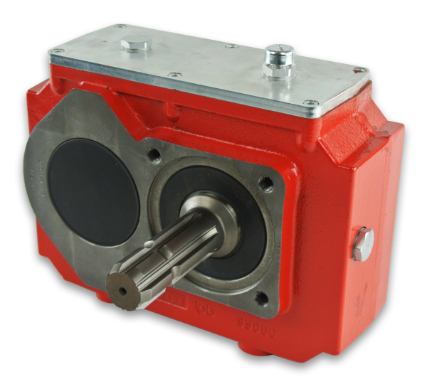
Challenges in Using Miter Gearboxes
While miter gearboxes offer various advantages, they also come with certain challenges that need to be addressed:
Lubrification: Proper lubrication is crucial for miter gearboxes to minimize friction, heat, and wear between gear teeth. Ensuring consistent and sufficient lubrication in the gearbox can be challenging, especially in enclosed or hard-to-reach spaces.
Maintenance: Miter gearboxes require periodic maintenance to ensure their optimal performance and longevity. Maintenance tasks may include checking and replenishing lubrication, inspecting gear teeth for wear, and addressing any misalignment or mounting issues that may arise over time.
Backlash: Backlash, or the clearance between gear teeth, can impact the accuracy of motion transfer. Excessive backlash can lead to reduced precision and positioning errors in applications that require high accuracy.
Complex Design: Miter gearboxes have a more intricate design compared to some other gearbox types, which can make manufacturing, assembly, and maintenance more complex. This complexity may also result in higher manufacturing and maintenance costs.
Efficiency Loss: Miter gearboxes can experience efficiency losses due to factors such as friction and misalignment. These losses can reduce the overall efficiency of power transmission, leading to energy wastage.
Space Constraints: In some applications, space limitations can pose a challenge when integrating miter gearboxes, especially when larger gear ratios are required to achieve the desired motion direction change.
Shock Loads: Applications subject to sudden shock loads or high impact forces can pose challenges for miter gearboxes. Adequate measures, such as using shock-absorbing components or designing for higher durability, may be required to address these challenges.
Alignment and Mounting: Proper alignment and mounting of miter gearboxes are critical to ensure smooth operation and prevent premature wear. Achieving precise alignment can be challenging, especially in installations with limited access or complex geometries.
Cost Considerations: The design complexity and manufacturing requirements of miter gearboxes can contribute to higher costs compared to simpler gearbox types. Balancing the benefits of miter gearboxes with the associated costs is essential during the selection process.
Addressing these challenges often requires careful engineering, proper maintenance practices, and consideration of specific application requirements. Despite the challenges, miter gearboxes remain valuable components in various industries where their unique motion direction-changing capabilities are advantageous.
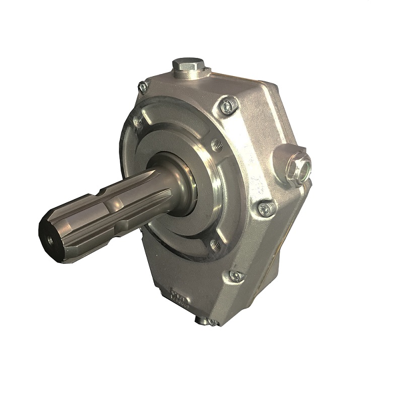
Boîtes de vitesses à engrenages coniques dans les applications automobiles, notamment les systèmes de direction
Les réducteurs à engrenages coniques jouent un rôle crucial dans les applications automobiles, notamment dans les systèmes de direction, où ils permettent de modifier la direction du mouvement de 90 degrés. Voici comment fonctionnent les réducteurs à engrenages coniques dans les systèmes de direction automobile :
Mécanisme de direction : Dans les véhicules, la colonne de direction assure le mouvement de rotation, qui doit être transmis aux roues à angle droit pour une direction efficace. Des boîtes de vitesses à renvoi d'angle sont intégrées au système de direction pour réaliser cette transformation.
Changement angulaire : Les réducteurs à engrenages coniques reçoivent le signal de rotation de la colonne de direction et le transmettent par l'intermédiaire d'engrenages coniques disposés à angle droit. Ceci permet de diriger le mouvement vers la tringlerie de direction et, finalement, vers les roues.
Précision et exactitude : Les systèmes de direction automobile exigent un contrôle précis et réactif du mouvement. Les boîtes de vitesses à engrenages coniques assurent une transmission précise du mouvement, permettant aux conducteurs de bénéficier d'une direction fiable et souple.
Conception compacte : Les boîtes de vitesses à onglets présentent une conception compacte et peu encombrante, ce qui les rend adaptées à une installation dans l'espace limité de la colonne de direction d'un véhicule.
Réduction des réactions négatives : Pour garantir la sécurité et la réactivité, les boîtes de vitesses à onglets sont conçues pour minimiser le jeu, ce qui est crucial pour maintenir un contrôle précis de la direction du véhicule.
Durabilité: Les applications automobiles exigent durabilité et fiabilité. Les réducteurs Miter sont conçus pour résister aux conditions et aux charges rencontrées dans les véhicules, garantissant ainsi des performances durables.
Les boîtes de vitesses à onglets contribuent au fonctionnement efficace des systèmes de direction des véhicules, offrant aux conducteurs le contrôle nécessaire pour une conduite sûre et confortable.
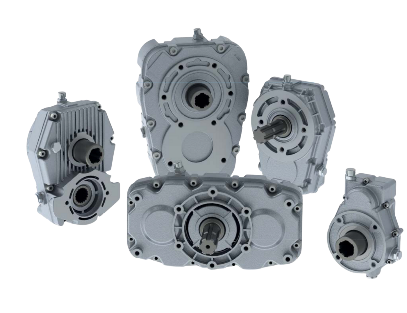
Transmission d'un mouvement à angle de 90 degrés par engrenages coniques dans une boîte de vitesses à onglet
Dans un réducteur à engrenages coniques, les engrenages coniques sont spécialement conçus pour transmettre un mouvement à angle droit entre les arbres qui se croisent. Ceci est rendu possible grâce au profil et à la disposition uniques des dents des engrenages coniques.
Les engrenages coniques possèdent des dents coniques dont la pointe s'affine vers le sommet du cône. Dans un réducteur à engrenages coniques, deux engrenages coniques à denture identique sont montés sur des arbres qui se croisent à angle droit. L'orientation des dents permet un engrènement fluide et la transmission du mouvement d'un arbre à l'autre, avec un changement de sens de rotation de 90 degrés.
Lorsqu'un engrenage conique tourne, ses dents coniques s'engrènent avec celles du second engrenage conique, ce qui entraîne la rotation du second arbre perpendiculairement au premier. Le rapport d'engrenage et la configuration des dents déterminent la relation entre la vitesse et le couple des arbres d'entrée et de sortie.
De manière générale, la conception précise des engrenages coniques et leur disposition dans une boîte de vitesses à engrenages coniques permettent une transmission efficace et fiable du mouvement à angle droit, ce qui les rend parfaitement adaptés aux applications nécessitant des changements de direction au sein de systèmes mécaniques.


editor by CX 2023-11-30