
Descrizione del prodotto
Basic Info.
| Modello | 1204 Wheel Tractor | |
| Drive Type | 4WD/2WD | |
| Overall MachineDimensions(length*width*height and location) | mm | 4200*1760*2700 |
| Wheelbase | mm | 2100 |
| commonly used wheel tracks | mm | 1400 |
| wheel distance(front wheel/rear wheel) | mm | 1300-1600(adjustable) |
| Minimum ground clearance and location | mm | 460(bottom of front axle) |
| rear axle | / | TB aggravation large bridge(12+12) |
| standard weight(front/rear) | kg | 144/400 |
| number of gears(forward/reverse) | / | 12+12 shuttle side gear |
| Maximum design theoretical speed | km/h | 48 |
| Engine and main clutch connection method | / | direct |
| type of rollover protection device(cab or safety frame) | / | security framework |
| Engine structure type | / | In-line,direct injection,water-cooled,four-stroke |
| engine manufacturer | / | HangZhou 120 Hp |
| engine air intake method | / | turbocharging |
| number of engine cylinders | / | 4 |
| engine standard power | kw | 88.2 |
| engine standard speed | r/min | 2400 |
| engine cooling method | / | water cooling |
| steering system type | / | fully hydraulic |
| steering system steering control mechanism | / | steering wheel |
| steering system steering mechanism type | / | front wheel steering |
| tyre model | front wheel:9.5-24 rear wheel:14.9-30 | |
| Suspension device type | / | Rear three-point suspension |
| number of hydraulic output groups | / | three |
| working device safety valve full opening pressure | MPa | 17.5-18.0 |
| number of splinesof PTO shaft | / | 6 |
| PTO shaft standard speed | R/min | 540/760 |
Parametri del prodotto
1204 TRACTOR
Tractor A self-propelled engine used to pull and drive work machinery to complete various mobile operations. Can also do fixed work power. It is composed of engine, transmission, walking, steering, hydraulic suspension, power output, electrical instruments, driving control and traction systems or devices.
The engine power is transmitted from the transmission system to the driving wheel to make the tractor run. In real life, it is common to use the rubber belt as the medium of power transmission. Agricultural, industrial and special purpose tractors according to function and use; According to the structure type of wheel, crawler, boat tractor and self-propelled chassis.
Features
1.It is equipped with famous and excellent engines, with large torque reserve, strong power and low fuel consumption.
2.Full hydraulic steering system, flexible and light to operate.
3.Middle shift gear, easy to operate.
4.8+2 gear shift, reasonable speed matching, high working efficiency and strong adaptability.
5.The new miniature LCD instrument is developed according to the harsh working conditions of construction machinery and has high reliability.
REAL SCENE SHOOTING
Although the tractor is a more complex machine, its type and size are different, but they are composed of 3 parts of the engine, chassis and electrical equipment, each of which is indispensable.
Tractor engine
It is the device that generates the power of the tractor, and its role is to convert the heat energy of the fuel into mechanical energy to output power. Most of the farm tractors produced use diesel engines.
Tractor chassis
It is the device that transmits power to the tractor. Its role is to transfer the power of the engine to the driving wheel and the working device to make the tractor travel, and to complete the mobile operation or fixed role. This function is achieved through the mutual cooperation and coordination of the transmission system, walking system, steering system, braking system and working device, and at the same time, they constitute the skeleton and body of the tractor. Therefore, we refer to the above 4 systems and 1 device as chassis. That is to say, in the whole of the tractor, all other systems and devices other than the engine and electrical equipment are collectively referred to as the tractor chassis.
Tractor electrical equipment
It is a device to ensure that the tractor uses electricity. Its role is to solve lighting, safety signals and engine starting.
Profilo Aziendale
HangZhou Qingcha Machinery Manufacturing Co., Ltd. is located in the ash high-tech park of Xihu (West Lake) Dis. Town, HangZhou City,HangZhou. It has been committed to the research and development and production of internal combustion counterbalanced forklifts, battery counterbalanced forklifts, OMV intelligent omnidirectional forklifts,wheel loader,mini dumper,mixer,backhoe loader,excavator ,tractor and mini digger.
Since its inception, the company has always been to build China’s most cost-effective high-quality construction machinery for the purpose of continuous research and development and innovation, the company has large CNC cutting machine, vertical machining center, horizontal gantry milling machine and other equipment more than 40 sets, to achieve all the key components Self-made, providing a strong guarantee for the quality of the product.
For the long-term development of the company, the company regards the quality as the life of the company, establishes a perfect quality assurance system, and has passed the IS09001 international quality system certification.
In the near future, HangZhou Forklift will become 1 of the CHINAMFG R&D, production and export construction machinery bases in the industry, contributing to the prosperity of the domestic and international logistics market and the promotion of innovation and development in the construction machinery industry.
Domande frequenti
1.What services would you offer if I buy from you?
Our trained Professional service team offers high-quality in-time service in a very friendly way. For a good customer.
2.Can you supply the machine with your customer requirement?
We have strong technology team, are able to do adjustment design for customers according to users’ most requirements.
3.Are you the factory?
Yes, the factory Founded in 2015 year.
Location at: Intersection of Huibu Xihu (West Lake) Dis. Avenue and CHINAMFG Avenue in Xihu (West Lake) Dis. Town, HangZhou City, HangZhou.
| Tipo: | Wheel Tractor |
|---|---|
| Utilizzo: | Farm Tractor, Garden Tractor, Lawn Tractor |
| Certification: | ISO, CE |
.shipping-cost-tm .tm-status-off{background: none;padding:0;color: #1470cc}
| Costi di spedizione: Trasporto stimato per unità. | informazioni sui costi di spedizione e sui tempi di consegna stimati. |
|---|
| Metodo di pagamento: |
|
|---|---|
| Pagamento iniziale Pagamento completo |
| Valuta: | US$ |
|---|
| Resi e rimborsi: | Puoi richiedere un rimborso entro 30 giorni dalla ricezione dei prodotti. |
|---|
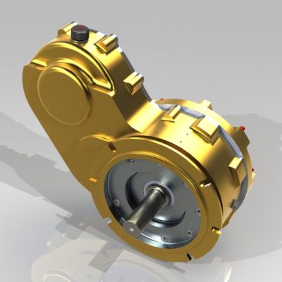
Installazione e allineamento corretti degli ingranaggi obliqui
Installare e allineare correttamente un riduttore per troncatrice è essenziale per garantirne prestazioni ottimali e lunga durata. Seguire questi passaggi per ottenere un'installazione e un allineamento corretti:
- Preparazione: Raccogliere tutti gli strumenti e le attrezzature necessari per l'installazione, tra cui hardware di montaggio, spessori e strumenti di allineamento.
- Superficie di montaggio: Assicurarsi che la superficie di montaggio sia pulita, piana e priva di detriti o contaminanti che potrebbero compromettere l'allineamento e il funzionamento del cambio.
- Strumenti di allineamento: Utilizzare strumenti di allineamento di precisione, come comparatori a quadrante o sistemi di allineamento laser, per misurare e regolare con precisione l'allineamento del cambio e dei suoi alberi di ingresso e di uscita.
- Controllare il parallelismo: Allineare gli alberi di ingresso e di uscita del cambio in modo che siano paralleli tra loro e perpendicolari alla superficie di montaggio. Questo passaggio è fondamentale per prevenire l'usura causata da disallineamenti e ridurre il gioco.
- Regolazione: Utilizzare spessori o altri componenti regolabili per perfezionare l'allineamento. Effettuare regolazioni incrementali controllando costantemente l'allineamento con gli strumenti di allineamento scelti.
- Carichi portanti: Assicurarsi che i cuscinetti che supportano gli alberi del cambio siano adeguatamente lubrificati e precaricati secondo le raccomandazioni del produttore. Un corretto precarico dei cuscinetti aiuta a mantenere l'allineamento e riduce l'usura.
- Bulloni di serraggio: Serrare i bulloni di montaggio gradualmente e in modo uniforme per evitare di introdurre ulteriori disallineamenti durante il processo di installazione.
- Scorrimento e gioco: Verificare eventuali problemi di eccentricità o gioco durante la rotazione ruotando l'albero di ingresso. In caso di inceppamenti, interferenze o rumori anomali, indagare e risolvere la causa prima di completare l'installazione.
- Controlli finali: Controllare nuovamente l'allineamento utilizzando gli strumenti di allineamento e assicurarsi che il cambio funzioni senza intoppi, senza vibrazioni, rumori o resistenze insolite.
- Documentazione: Conservare un registro delle misurazioni di allineamento e delle regolazioni effettuate durante l'installazione. Questa documentazione può essere utile per future consultazioni e manutenzioni.
L'installazione e l'allineamento corretti dei riduttori angolari contribuiscono a ottimizzarne le prestazioni, a ridurre al minimo l'usura e a contribuire all'efficienza e all'affidabilità complessive del sistema meccanico in cui vengono utilizzati.
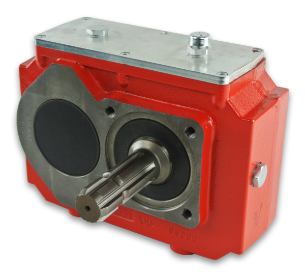
Differenze tra i riduttori obliqui e altri tipi di riduttori
I riduttori angolari presentano caratteristiche distintive che li differenziano da altri tipi di riduttori, come i riduttori elicoidali, a denti dritti e i riduttori epicicloidali. Queste differenze contribuiscono alle loro capacità uniche e alla loro idoneità per applicazioni specifiche:
- Disposizione degli ingranaggi: I riduttori a 45° utilizzano ingranaggi conici che si intersecano a 90 gradi. Al contrario, i riduttori elicoidali e cilindrici utilizzano disposizioni di ingranaggi parallele o complanari, mentre i riduttori epicicloidali presentano più ingranaggi disposti attorno a un ingranaggio centrale centrale.
- Cambiamento della direzione del movimento: I riduttori angolari sono eccellenti nel cambiare la direzione del movimento rotatorio di 90 gradi. Altri riduttori possono cambiare la direzione del movimento di angoli diversi o mantenere la stessa direzione.
- Compattezza: I riduttori angolari sono noti per il loro design compatto, che li rende adatti ad applicazioni con spazi limitati. I riduttori epicicloidali, pur essendo compatti, presentano una struttura interna diversa.
- Controllo del gioco: I riduttori angolari sono progettati per ridurre al minimo il gioco e garantire una trasmissione precisa del movimento. I riduttori elicoidali e cilindrici possono presentare un gioco maggiore a causa della disposizione degli ingranaggi, mentre i riduttori epicicloidali possono offrire un buon controllo del gioco.
- Coppia e velocità: I diversi riduttori variano in termini di coppia e velocità. I riduttori angolari sono adatti per applicazioni con coppia e velocità moderate, mentre i riduttori epicicloidali offrono un'elevata densità di coppia.
- Applicazioni: I riduttori angolari sono comunemente utilizzati per applicazioni che richiedono cambi di direzione di 90 gradi, come sistemi di trasporto, macchine da stampa e alcuni tipi di apparecchiature industriali. I riduttori elicoidali e cilindrici sono diffusi in vari macchinari e attrezzature. I riduttori epicicloidali trovano impiego in robotica, industria aerospaziale e macchinari pesanti.
Ogni tipo di riduttore ha i suoi vantaggi e viene scelto in base ai requisiti specifici dell'applicazione, tra cui vincoli di spazio, precisione del controllo del movimento, coppia e velocità.
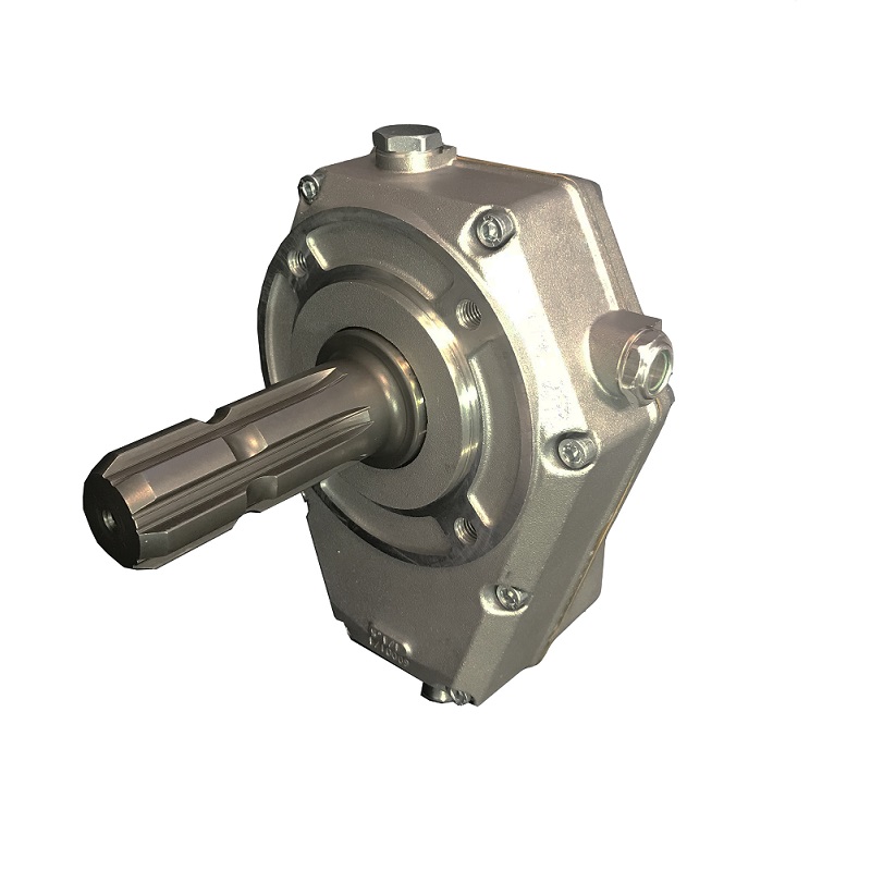
Changing Direction of Rotational Motion with Miter Gearboxes
Miter gearboxes are specialized mechanical devices designed to efficiently change the direction of rotational motion by 90 degrees. They achieve this transformation through the use of bevel gears with intersecting shafts:
- Bevel Gears: Miter gearboxes utilize bevel gears, which have conical-shaped teeth. These gears are cut at an angle to the gear’s face and allow the transmission of motion between two intersecting shafts positioned at a 90-degree angle to each other.
- Intersecting Shafts: The input and output shafts of a miter gearbox are positioned in such a way that they intersect at a right angle. The bevel gears are mounted on these shafts, and when the input shaft rotates, it engages with the teeth of the bevel gear on the output shaft, transferring motion at a right angle.
- Directional Change: As the input shaft rotates, the bevel gear’s teeth mesh and transmit motion from the input shaft to the output shaft. This interaction causes a change in the direction of rotation, redirecting the output motion perpendicular to the input motion.
- Compact Design: Miter gearboxes are known for their compact and space-saving design. The intersecting shafts and bevel gears are housed within the gearbox casing, allowing for efficient motion redirection without the need for additional external components.
Overall, miter gearboxes play a crucial role in changing the direction of rotational motion, making them essential components in various mechanical systems where motion needs to be redirected efficiently and precisely.


editor by CX 2023-11-20