Descrição do produto
Descrição do produto
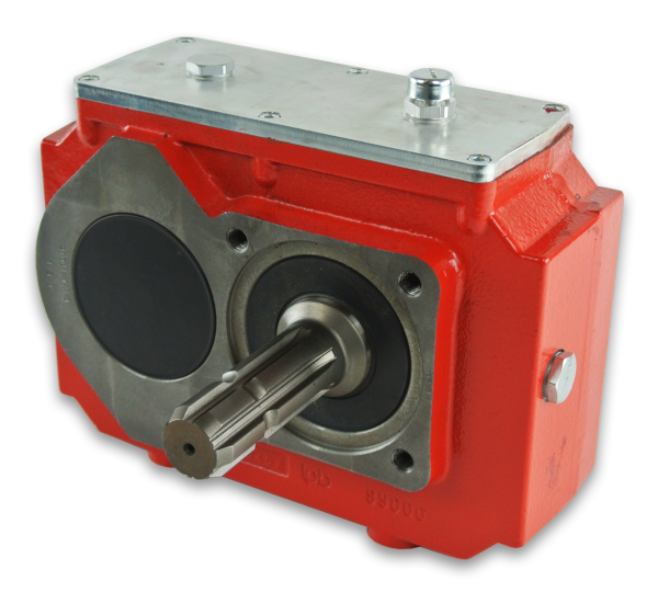
70mm 750W 25:1 low noise high torque pto gearbox for Cartesian robot for 5 axis machining center developed and manufactured by WEITENSTAN together with German and ZheJiang technicians for many years.
High precision miniature cycloidal gearbox has the characteristics of smaller, ultra-thin, lightweight and high rigidity, anti-overload and high torque. With good deceleration performance, smooth operation and accurate positioning can be achieved. Integrated design, can be directly connected with the motor, to achieve high precision, high rigidity, high durability and other advantages. It is designed for high speed ratio, high geometric accuracy, low motion loss, large torque capacity and high stiffness applications. The compact design (minimum OD ≈40mm, currently the world’s smallest precision cycloidal pin-wheel reducer) allows it to be installed in limited Spaces.
Reducer drawings
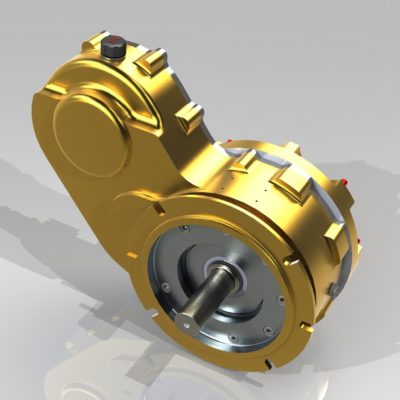
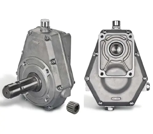
Fotos detalhadas
Product Advantage
70mm 750W 25:1 low noise high torque pto gearbox for Cartesian robot advantages:
1, fine precision cycloidal structure
Ultra flat shape is achieved through differential reduction mechanism and thin cross roller bearing, contributing to the compact size of the equipment. The combination of small size and unmatched superior parameters achieves the best combination of performance, price and size (high cost performance).
2. Excellent accuracy (transmission loss ≤1 arcmin)
Through the complex meshing of precision cycloid gear and high precision roller pin, higher transmission accuracy is achieved while maintaining small size and high speed ratio.
3, high rigidity
Increase the mesh rate to disperse the load, so the rigidity is high.
4. High overload capacity
It maintains trouble-free operation under abnormally low noise and vibration conditions while ensuring excellent overturning and torsional stiffness parameters. Integrated axial radial cross roller bearings, high load capacity and overload capacity of the reducer, can ensure users to provide a variety of temperature range of applications.
5, the motor installation is simple
Electromechanical integration design, can be directly connected with the motor, any brand of motor can be installed directly, without adding any device.
6. Maintenance free
Seal grease to achieve maintenance free. No refueling, no mounting direction restrictions.
7, stable performance
The manufacturing process of high wear-resistant materials and high precision parts has been certified by ISO9000 quality system, which guarantees the reliable operation of the reducer.
Product Classification
WF Series
High Precision Miniature Reducer
WF series is a high precision micro cycloidal reducer with flange, which has a wide range of applications. This series of reducers includes precise reduction mechanisms and radial – axial roller bearings. The unique design allows load to act directly on the output flange or housing without additional bearings. WF series reducer is characterized by module design, can be installed through the flange motor and reducer, belongs to the motor directly connected reducer.
WFH Series
High Precision Miniature Reducer
WFH series is a hollow form of high precision miniature cycloidal reducer, wire, compressed air pipeline, drive shaft can be through the hollow shaft, non-motor direct connection type reducer. The WFH series is fully sealed, full of grease and includes precise deceleration mechanism and radial – axial roller bearings. The unique design allows load to be acted directly on the output flange or housing without additional bearings.
Parâmetros do produto
| Size | reduction ratio | Rated output moment | Allowable torque of start and stop | Instantaneous allowable moment | Rated input speed | Maximum input speed | Tilt stiffness | Torsional stiffness | No-load starting torque | Transmission accuracy | Error accuracy | Moment of inertia | Peso | |
| Axis rotation | Shell rotation | Nm | Nm | Nm | rpm | rpm | Nm/arcmin | Nm/arcmin | Nm | arcmin | arcmin | kg-m² | kg | |
| WF07 | 21 | 20 | 15 | 30 | 45 | 3000 | 6000 | 6 | 1.1 | 0.12 | P1≤±1 P2≤±3 | P1≤±1 P2≤±3 | 0.52 | 0.42 |
| 41 | 40 | 0.11 | 0.47 | |||||||||||
| WF17 | 21 | 20 | 50 | 100 | 150 | 3000 | 6000 | 28 | 6 | 0.21 | P1≤±1 P2≤±3 | P1≤±1 P2≤±3 | 0.88 | 0.85 |
| 41 | 40 | 0.18 | 0.72 | |||||||||||
| 61 | 60 | 0.14 | 0.69 | |||||||||||
| WF25 | 21 | 20 | 110 | 220 | 330 | 3000 | 5500 | 131 | 24 | 0.47 | P1≤±1 P2≤±3 | P1≤±1 P2≤±3 | 6.12 | 2 |
| 31 | 30 | 0.41 | 5.67 | |||||||||||
| 41 | 40 | 0.38 | 4.9 | |||||||||||
| 51 | 50 | 0.35 | 4.56 | |||||||||||
| 81 | 80 | 0.31 | 4.25 | |||||||||||
| WF32 | 25 | 24 | 190 | 380 | 570 | 3000 | 4500 | 240 | 35 | 1.15 | P1≤±1 P2≤±3 | P1≤±1 P2≤±3 | 11 | 4.2 |
| 31 | 30 | 1.1 | 10.8 | |||||||||||
| 51 | 50 | 0.77 | 9.35 | |||||||||||
| 81 | 80 | 0.74 | 8.32 | |||||||||||
| 101 | 100 | 0.6 | 7.7 | |||||||||||
| WF40 | 25 | 24 | 320 | 640 | 960 | 3000 | 4000 | 377 | 50 | 1.35 | P1≤±1 P2≤±3 | P1≤±1 P2≤±3 | 13.2 | 6.6 |
| 31 | 30 | 1.32 | 12.96 | |||||||||||
| 51 | 50 | 0.92 | 11.22 | |||||||||||
| 81 | 80 | 0.81 | 9.84 | |||||||||||
| 121 | 120 | 0.72 | 8.4 | |||||||||||
Instruções de Instalação
perfil de companhia
P: Tempo de substituição da graxa do redutor de velocidade
A: Ao utilizar a quantidade adequada de graxa e redutor, o tempo padrão de substituição é de 20.000 horas, dependendo do estado de envelhecimento da graxa. Além disso, quando a graxa estiver manchada ou for utilizada em condições de temperatura ambiente (acima de 40 °C), verifique o envelhecimento e a presença de incrustações na graxa e especifique o tempo de substituição.
P: Prazo de entrega
A: A Fubao possui mais de 2000 bases de produção, com uma produção diária superior a 1000 unidades, e os modelos padrão são entregues em até 7 dias.
P: Seleção do redutor
A: A Fubao oferece orientação profissional na seleção de produtos, com maior grau de adequação do produto, melhor relação custo-benefício e maior taxa de utilização.
P: Qual é a gama de aplicações do redutor?
A: A Fubao possui uma equipe profissional de pesquisa e desenvolvimento, com design completo para cada categoria, capaz de ser compatível com qualquer motor de passo ou servomotor, proporcionando uma compatibilidade mais precisa.
| Custo do frete: Frete estimado por unidade. | To be negotiated |
|---|
| Aplicativo: | Motor, Machinery, Agricultural Machinery, Humanoid Robot |
|---|---|
| Dureza: | Superfície dentária endurecida |
| Instalação: | Tipo vertical |
| Personalização: | Disponível | Solicitação personalizada |
|---|
Desafios na utilização de caixas de engrenagens de corte diagonal
Embora as caixas de engrenagens cônicas ofereçam diversas vantagens, elas também apresentam certos desafios que precisam ser abordados:
Lubrificação: A lubrificação adequada é crucial para as caixas de engrenagens cônicas, a fim de minimizar o atrito, o calor e o desgaste entre os dentes das engrenagens. Garantir uma lubrificação consistente e suficiente na caixa de engrenagens pode ser um desafio, especialmente em espaços fechados ou de difícil acesso.
Manutenção: As caixas de engrenagens cônicas requerem manutenção periódica para garantir seu desempenho ideal e longa vida útil. As tarefas de manutenção podem incluir a verificação e reposição da lubrificação, a inspeção dos dentes da engrenagem quanto ao desgaste e a correção de quaisquer problemas de desalinhamento ou montagem que possam surgir com o tempo.
Retaliação: A folga, ou o espaço entre os dentes da engrenagem, pode afetar a precisão da transmissão do movimento. Folga excessiva pode levar à redução da precisão e a erros de posicionamento em aplicações que exigem alta exatidão.
Projeto complexo: As caixas de engrenagens cônicas possuem um design mais complexo em comparação com outros tipos de caixas de engrenagens, o que pode tornar a fabricação, a montagem e a manutenção mais complexas. Essa complexidade também pode resultar em custos mais elevados de fabricação e manutenção.
Perda de eficiência: As caixas de engrenagens cônicas podem sofrer perdas de eficiência devido a fatores como atrito e desalinhamento. Essas perdas podem reduzir a eficiência geral da transmissão de potência, levando ao desperdício de energia.
Restrições de espaço: Em algumas aplicações, as limitações de espaço podem representar um desafio na integração de caixas de engrenagens cônicas, especialmente quando são necessárias relações de engrenagem maiores para obter a mudança de direção do movimento desejada.
Cargas de choque: Aplicações sujeitas a cargas de choque repentinas ou forças de impacto elevadas podem representar desafios para as caixas de engrenagens cônicas. Medidas adequadas, como o uso de componentes com amortecimento de impacto ou o projeto para maior durabilidade, podem ser necessárias para lidar com esses desafios.
Alinhamento e montagem: O alinhamento e a montagem corretos das caixas de engrenagens de esquadria são essenciais para garantir um funcionamento suave e evitar o desgaste prematuro. Obter um alinhamento preciso pode ser um desafio, especialmente em instalações com acesso limitado ou geometrias complexas.
Considerações sobre custos: A complexidade do projeto e os requisitos de fabricação das caixas de engrenagens cônicas podem contribuir para custos mais elevados em comparação com tipos de caixas de engrenagens mais simples. Equilibrar os benefícios das caixas de engrenagens cônicas com os custos associados é essencial durante o processo de seleção.
Superar esses desafios geralmente exige engenharia cuidadosa, práticas de manutenção adequadas e consideração dos requisitos específicos da aplicação. Apesar dos desafios, as caixas de engrenagens cônicas continuam sendo componentes valiosos em diversos setores industriais, onde suas capacidades exclusivas de mudança de direção do movimento são vantajosas.
Common Industries Using Miter Gearboxes and Their Applications
Miter gearboxes find application in various industries due to their ability to change the direction of rotational motion by 90 degrees. Some of the common industries where miter gearboxes are commonly used include:
- Automotive: Miter gearboxes are utilized in automotive applications for power transmission between different components, such as steering systems and drive shafts.
- Printing: Printing machinery uses miter gearboxes to change the direction of motion in the paper feed mechanism, ensuring accurate paper alignment.
- Material Handling and Conveyors: Miter gearboxes are used in conveyor systems to facilitate the transfer of materials at right angles.
- Manufacturing: Various manufacturing processes require motion direction changes, such as in assembly lines and automated equipment.
- Robotics: Miter gearboxes are employed in robotics for motion control, allowing robots to move efficiently and accurately in different directions.
- Woodworking: Woodworking machinery uses miter gearboxes to change the direction of cutting tools, enhancing precision and efficiency.
- Textile: Miter gearboxes are used in textile machinery to control the motion of fabrics and threads during manufacturing.
- Machine Tools: Miter gearboxes play a role in machine tools where angular motion changes are needed.
The unique design of miter gearboxes makes them suitable for applications requiring precise 90-degree motion changes, enabling smoother and more efficient operation in these industries.
Handling High-Speed and Heavy-Load Applications in Miter Gearboxes
Miter gearboxes are versatile mechanical components that can handle a wide range of applications, including both high-speed and heavy-load scenarios. The suitability of a miter gearbox for a specific application depends on various factors, including design, material, lubrication, and overall engineering considerations.
When it comes to high-speed applications, miter gearboxes can be designed and manufactured to handle rotational speeds that are typical in various industries. Properly designed miter gearboxes will consider factors such as gear tooth profile, lubrication, and material selection to minimize friction, heat generation, and wear, allowing for efficient and reliable operation at high speeds.
Similarly, miter gearboxes can also be engineered to handle heavy-load applications. By using durable materials, precision machining, and robust bearing arrangements, miter gearboxes can efficiently transmit high levels of torque while maintaining structural integrity. The bevel gear arrangement in miter gearboxes is well-suited for distributing heavy loads evenly across the gear teeth, ensuring smooth and consistent power transmission.
It’s important to note that the specific design and capabilities of a miter gearbox will vary depending on the manufacturer and the intended application. Engineers and designers work to optimize gear ratios, bearing arrangements, and housing materials to ensure that the miter gearbox can handle the demands of the given application, whether it involves high speeds, heavy loads, or a combination of both.
Ultimately, miter gearboxes can provide reliable performance across a wide spectrum of operating conditions, making them a versatile choice for various industries and applications.


editor by CX 2023-09-11